


WIFI-300 LED WiFi SPI Controller IC Dream Color Pixels LED Strip

LED-WiFi controller is following the traditional with infrared, RF technology controller foundation, it is birth of market and customer's demand, it is one type controller which integration the newest wifi technical in the market. It makes the LED control more convenience, more hommization. We can use an Android system or IOS system mobile phone to control.
 Low Stock 2 left
LED-WiFi controller is following the traditional with infrared, RF technology controller foundation, it is birth of market and customer's demand, it is one type controller which integration the newest wifi technical in the market. It makes the LED control more convenience, more convenient. We can use an Android system or IOS system mobile phone to install control software, then it can control LED, this is the wishes of every customer.
WIFI-300 LED WiFi SPI Controller;support LPD6803,TM1809,WS2801,WS2811,WS2812B,TLS3001,UCS1903, IC Dream Color Pixels LED Strips only! This is NOT for standard RGB or RGBW LED strips Only for addressable LED strips using the IC's listed above.
Use WiFi technology can make our control range more wider, can get rid of narrow space constraint,
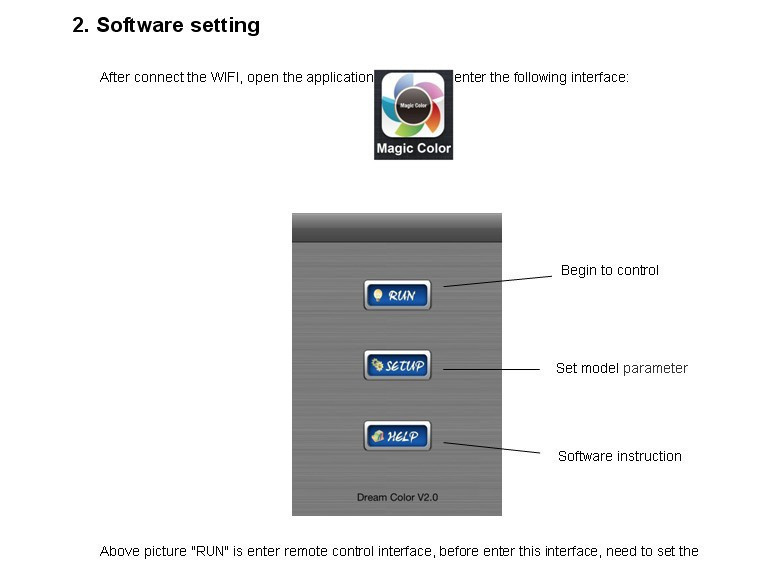
III Magic Color Instruction
1. WIFI Connect
After power on the controller, open the cellphone set of WIFI, search WIFI network, you will check WIFI equipment is named LN+number, for example"LN001", "LN003" and so on, as picture:
The number after LN is controller SSID code, same controller can set different code, when in the same network environment have many controllers, it can distinguish. About the SSID setting, will be in details below.


LED-WiFi Controller Function Instruction
1. Working state instruction
|
Indicator light |
Function table |
|
Power |
Power indicator light, long-time bright shows power supply normally |
|
Wifi |
Free time long-time bright, have wifi data enter flicker, configuration wifi Ssid off |
|
Link |
Have wifi date enter, then flicker, no wifi data, then off. |
|
RF |
Have RF remote data or press key operate, then flicker, free time off. |
2. Setting SSID number
The dial code is used for setting LED-WiFi controller Ssid number, corresponding table as below. Form 0 to 15, have 16 code in total, so our Ssid number fasten to LN001 to LN016. That means use our product in same small area can set 16 mutual isolation LAN, once the dial code changed after switch was dialed, Ssid number immediately be modified, so you need to note that it need to search and connect again.
|
code |
SSID |
|
0 |
LN001 |
|
1 |
LN002 |
|
2 |
LN003 |
|
3 |
LN004 |
|
4 |
LN005 |
|
5 |
LN006 |
|
6 |
LN007 |
|
7 |
LN008 |
|
8 |
LN009 |
|
9 |
LN010 |
|
A |
LN011 |
|
B |
LN012 |
|
C |
LN013 |
|
D |
LN014 |
|
E |
LN015 |
|
F |
LN016 |
3. Connect LED, Power supply port
LED Strip according model connect corresponding port.
4. Match Key function
The first time use the controller and remote control, maybe because the controller address and remote control address is not match, it will cause the remote control can not control, at this time, it need to use this button to make this 2 address matched.
Use method: first, press the controller "Match" key, at the same time press any key of the remote control, more than 2s, now the remote control indicator light RF will flicker 3 times, release "Match" key, then finished.
5. Function key function
“Function” key is a composite button, it have switch and mode change function.
Function instruction: long-time(more than 2s): on off;
Short press(less than 1s): mode change.
1. Controller panel have 64 touch point, and the function as follow:
1. ON/OFF,you can turn on/off controller output at any time;
2. Pause,at dynamic mode, you can stop the controller at the current state;
3. This button have 2 functions :
Mode + choice key, when current control pattern is pulley pattern (color), if must
realize the pattern (color)in the controller, can press this key.
mode switch button, for the current control mode, you can switch M + key which
is specified mode (color) in the table.
4. This button have 2 functions :
Mode - choice key,when current control pattern is pulley pattern (color), if must
realize the pattern (color)in the controller, can press this key.
mode switch button,For the current control mode, you can switch M + key which
is specified mode (color) in the table.
5. The output brightness control key,every time you press this button, the brightness series
add 1,altogether 32 levels.
6. The output brightness control key,every time you press this button, the brightness series
minus 1, altogether 32 levels.
7. The output speed control key,every time you press this button, the brightness series
add 1, altogether 99 levels.
8. The output speed control key,every time you press this button, the brightness series
minus 1, altogether 99 levels.
9. Color pulley touch button, static mode choose button, up to 55 touch points.
this button have 2 functions:
static color choose button, when current control mode is the mode of M
key(color), if you want to realize static color ,can press this button.
pulley color choose button, can choose from 55 kinds of static mode
(the color from pulley).
2. Power supply management: stop to use the remote more than 20s, the remote will enter the
standby state (untouchable state), to extend the battery life; slightly shake once, then the
remote will come back to the normal working state (touchable state).
Notice:This remote control only can change the pattern, the brightness, the speed, if you want
to change the controller IC model, the IC support point, the RGB sequency, then must
connect WIFI through cell phone to change.
7. Controller built-in mode table
|
Modes |
Mode instruction |
|
1 |
Static red |
|
2 |
Static green |
|
3 |
Static blue |
|
4 |
Static yellow |
|
5 |
Static purple |
|
6 |
Static cyan |
|
7 |
Static white |
|
8 |
Red horse race to right |
|
9 |
Red horse race to left |
|
10 |
Green horse race to right |
|
11 |
Green horse race to left |
|
12 |
Blue horse race to right |
|
13 |
Blue horse race to left |
|
14 |
Red horse race lower curtain |
|
15 |
Green horse race draw curtain |
|
16 |
Three base color horse race brush forward direction |
|
17 |
Three mixing color horse race brush |
|
18 |
Three base color horse race brush draw curtain |
|
19 |
Three mixing color horse race brush lower curtain |
|
20 |
Seven-color horse race brush forward direction |
|
21 |
Seven-color horse race brush backward direction |
|
22 |
Seven-color horse race brush draw curtain |
|
23 |
Seven-color horse race brush lower curtain |
|
24 |
Three base color brush forward direction |
|
25 |
Three base color brush backward direction |
|
26 |
Three mixing color brush forward direction |
|
27 |
Three mixing color brush backward direction |
|
28 |
Seven-color brush forward direction |
|
29 |
Seven-color brush backward direction |
|
30 |
Three base color brush draw curtain |
|
31 |
Three base color brush lower curtain |
|
32 |
Seven-color brush draw curtain |
|
33 |
Seven-color brush lower curtain |
|
34 |
Three base color stroboflash |
|
35 |
Seven-color stroboflash |
|
36 |
Three base color jumpy change |
|
37 |
Three mixing color jumpy change |
|
38 |
Seven-color jumpy change |
|
39 |
Green-blue-yellow three color wave by wave running forward direction |
|
40 |
Blue-yellow-cyan three color wave by wave running backward direction |
|
41 |
Three mixing color three color wave by wave running forward direction |
|
42 |
Three mixing color three color wave by wave running backward direction |
|
43 |
Blue-yellow-cyan three color wave by wave running forward direction |
|
44 |
Green-blue draw curtain |
|
45 |
Blue-yellow lower curtain |
|
46 |
Seven-color wave forward direction |
|
47 |
Seven-color wave backward direction |
|
48 |
Blue trail backward direction |
|
49 |
Red trail forward direction |
|
50 |
Red trail backward direction |
|
51 |
Green trail forward direction |
|
52 |
Green trail backward direction |
|
53 |
Blue trail forward direction |
|
54 |
Yellow trail forward direction |
|
55 |
Cyan trail forward direction |
|
56 |
Purple trail backward direction |
|
57 |
White trail forward direction |
|
58 |
White trail backward direction |
|
59 |
Seven-color running trail backward direction |
|
60 |
Seven-color running trail forward direction |
|
61 |
Change color cyan-red-cyan forward direction |
|
62 |
Change color purple-red-purple forward direction |
|
63 |
Change color purple-red-purple backward direction |
|
64 |
Change color yellow-green-yellow forward direction |
|
65 |
Change color yellow-green-yellow backward direction |
|
66 |
Change color cyan-green-cyan forward direction |
|
67 |
Change color cyan-green-cyan backward direction |
|
68 |
Change color purple-blue-purple forward direction |
|
69 |
Change color purple-blue-purple backward direction |
|
70 |
Change color cyan-blue-cyan forward direction |
|
71 |
Change color cyan-blue-cyan backward direction |
|
72 |
Change color white-red-white forward direction |
|
73 |
Change color white-red-white backward direction |
|
74 |
Change color green-red-green forward direction |
|
75 |
Change color blue-red-blue backward direction |
|
76 |
Change color yellow-red-yellow forward direction |
|
77 |
Change color yellow-red-yellow backward direction |
|
78 |
Change color red-yellow-red |
|
79 |
Change color red-purple-red |
|
80 |
Change color green-cyan-green |
|
81 |
Change color green-yellow-green |
|
82 |
Change color blue-purple-blue |
|
83 |
Automatically play 8-82 |
nstall power supply and LED equipment
This connector structure belong to drawer structure, the device interface of power supply and LED is together, four interface one the left side (GND,CLK,DATA, LAT)is connect led equipment, the fifth interface is connect the anode V+ of power supply, the sixth interface is connect the cathode V- of power supply. This controller now can support 10 kinds of SPI strip in market, As follows:
|
Number |
Model |
Signal line |
|
1 |
LPD6803 |
DATACLK |
|
2 |
TM1803 |
DATA |
|
3 |
UCS1903 |
DATA |
|
4 |
WS2811 |
DATA |
|
5 |
TM1812 |
DATA |
|
6 |
TM1809 |
DATA |
|
7 |
WS2801 |
DATACLK |
|
8 |
TLS3001 |
DATA |
|
9 |
TLS3008 |
DATA |
|
10 |
P9813 |
DATACLK |
Wiring as WS2811 UCS1903
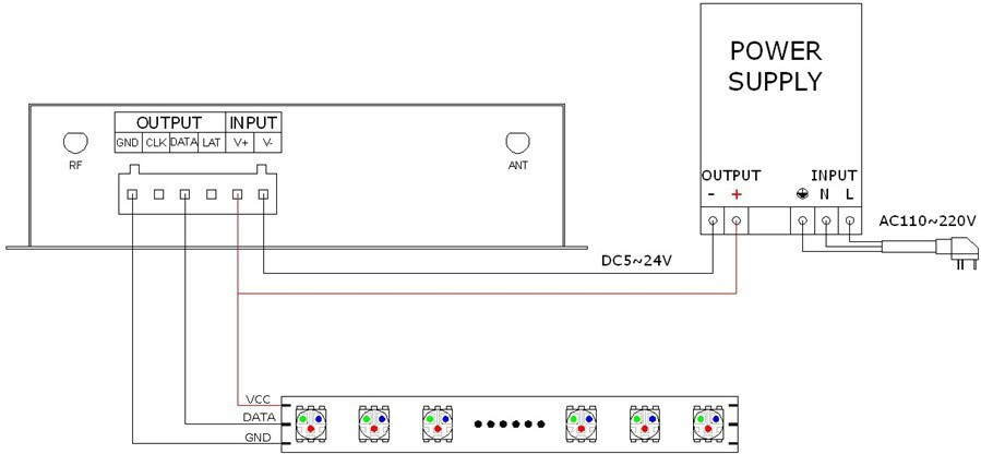
Wiring as WS2801 LPD6803 etc.

Remote control technical parameters
1:Working temperature:-20-60
2:Power supply method:AAA*3
3:Supply voltage:1.5V*3
4:Standby power:0.015mW
5:Standby current:3uA
6:Working current:200uA
7:Emission current:10mA
8:Remote control distance:about 30m
9:Standby time:6 month
2. Software technical parameters
1:Name:Magic Color
2:Runtime platform: Android version support Android system(better one can support Samsung,
HTC), IOS version support IOS system, equipment must have WiFi function.
3:Language: English
4:Category: communications
5:Free, green, no plug-ins
3. Controller technical parameters
1:Working voltage: DC5--24V
2:Output control: SPI signal output
3:Output current: 4A*3
4:Connect mode: SPI signal wires(DATA, CLK)
5:External dimension: L107*W65*H30(mm)
6:Receiving sensitivity: 802.11b DSSS(-5dBm),802.11b CCK (-10dBm),802.11g
OFDM(-15dBm)
Questions & Answers

 Download PDF
 SAME DAY SHIPPING
Most orders ship same day or use our Rush Service.
100% SATISFACTION
Our promise you will always be happy with your purchase.
ONLINE SUPPORT 24/7
Use Email, chat or phone for any tech or order help.

